
1 Introduction
The real world and its mirror image are plane-symmetric to each other with respect to the surface of the mirror. However, an object and its mirror image do not necessarily appear plane-symmetric because human visual perception can be distorted due to optical illusions [1 R. Gregory, The intelligent eye. Weidenfeld & Nicolson, London (1970) , 3 J. Ninio, The science of illusions (English translation). Cornell University Press, Ithaca (2001) ]. One typical case is a left-right reversal illusion [9 K. Sugihara, Anomalous mirror symmetry generated by optical illusion. Symmetry 8, Article ID 21, DOI 10.3390/sym8040021 (2016) ]. An example is shown in Figure 1, where an object is placed on a desk and a mirror is placed vertically behind it. The object is an arrow pointing to the right, but it points to the left in the mirror. We call this class of objects the “left-right reversing objects.” Their behaviors look impossible, and hence they belong to the class of “impossible objects” [11 K. Sugihara, Family tree of impossible objects created by optical illusion. In Brindges 2020 Conference Proceedings, 329–336, http://archive.bridgesmathart.org/2020/bridges2020-329.pdf (2020) ].

In this article, we focus on left-right reversing objects. We first show the mathematics behind them, and then present a method for designing such objects with desired appearances. Next, we exhibit two simple subclasses, which can be constructed using paper and hence can be useful even for children to create their own illusion objects.
2 Left-right reversal created by line-symmetric objects
Let be a set of points in the 3D space, be a straight line, and be the set of points obtained by rotating around by 180°. If , is said to be line-symmetric with respect to , and is called a line of symmetry.

Suppose that we fix a line-symmetric object in space in such a way that the line of symmetry is vertical, as shown in Figure 2 (a), where the dot-dashed line represents the line of symmetry. Let and be two viewing directions that are parallel to a common plane containing the line of symmetry, with these views directed towards the object from opposite sides, with the same downward angle. Then looks the same when we see it from the directions and . This is the basic nature of a line-symmetric object. As shown in Figure 2 (b), if we use a vertical mirror and see the reflected image along the direction instead of seeing it directly along , the left and right will be exchanged. Thus, if the original appearance along is a right-facing arrow, the appearance along will be a left-facing arrow.
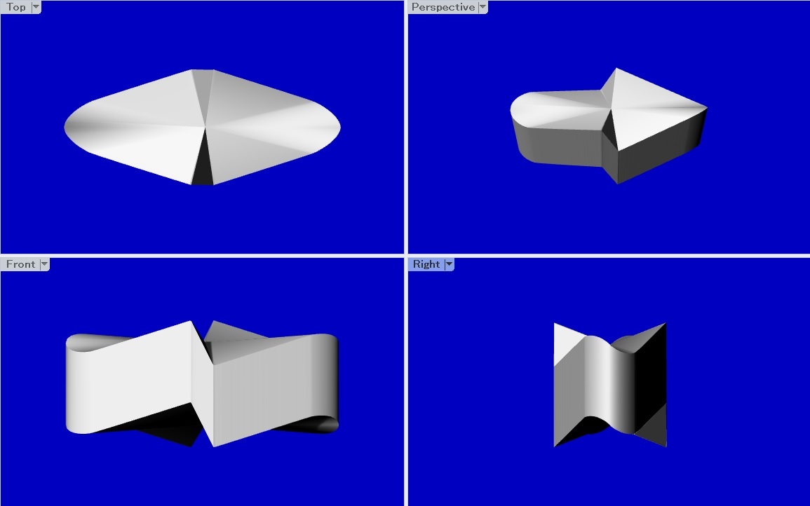
Indeed, this optical process is seen in Figure 1. Figure 3 shows computer graphics images of the object. The left top is the plan view, from which we can see that the boundary of the object is point-symmetric with respect to the center. The line of symmetry of this object passes through the center and is perpendicular to the image plane. The left bottom image is the front view, and the right bottom image is the side view. From those images we may deduct that the object is line-symmetric with respect to a vertical line. The top right image shows the appearance along the special viewing direction, which makes the object look like a right-facing arrow.
As this example demonstrates, once we have a line-symmetric object, we can produce a left-right reversal illusion. The next question is how to create a line-symmetric object having a desired appearance.
3 How to produce a desired appearance
Let be a Cartesian coordinate system in 3D space. Figure 4 shows this coordinate system in such a way that the left half shows the -plane and the right half shows the -plane, with the common vertical -direction. Suppose that, as shown in the left part of Figure 4, we fix two -monotone curves, and , , on the -plane that satisfy , , and for . Let denote the closed curve composed of these two curves, and denote the curve obtained when we rotate by 180° around the -axis. In Figure 4, is represented by broken lines.

Our goal is to find the space curve, say , that coincides with when seen along the viewing direction and with when seen along the viewing direction . In Figure 4, we take the right-facing arrow as the curve , and then , . However, this condition is not necessary in general; that is, the curve is not necessarily symmetric with respect the -axis.
For an arbitrary , we consider two points and . When we rotate by 180° around the origin, is transformed into , and hence and align along the same line parallel to the -axis.
Let denote the point that matches when seen along and matches when seen along . As shown on the right side of Figure 4, the point that matches when seen along the direction is on a line passing through and parallel to . This point is represented by
In its turn, the point that matches when seen in the direction is on the line passing through and parallel to . This point is represented by
The point is obtained by setting (). This yields the formula
and substituting this expression in the formula for , we obtain
Finally, we obtain
As moves from to , the point traces a space curve that we denote by . Let be the curve that is line-symmetric to with respect to the -axis. Then
where .
The curves and together form a closed space curve denoted by , which is our objective. That is, coincides with when seen along and coincides with when seen along .
We constructed the 3D object in Figure 1 by first computing the space curve from the boundary of an arrow shape using the above method, then translating in the vertical direction (the direction parallel to the -axis) and obtaining the swept cylindrical surface, and finally by wrapping the top and the bottom with continuous surfaces.
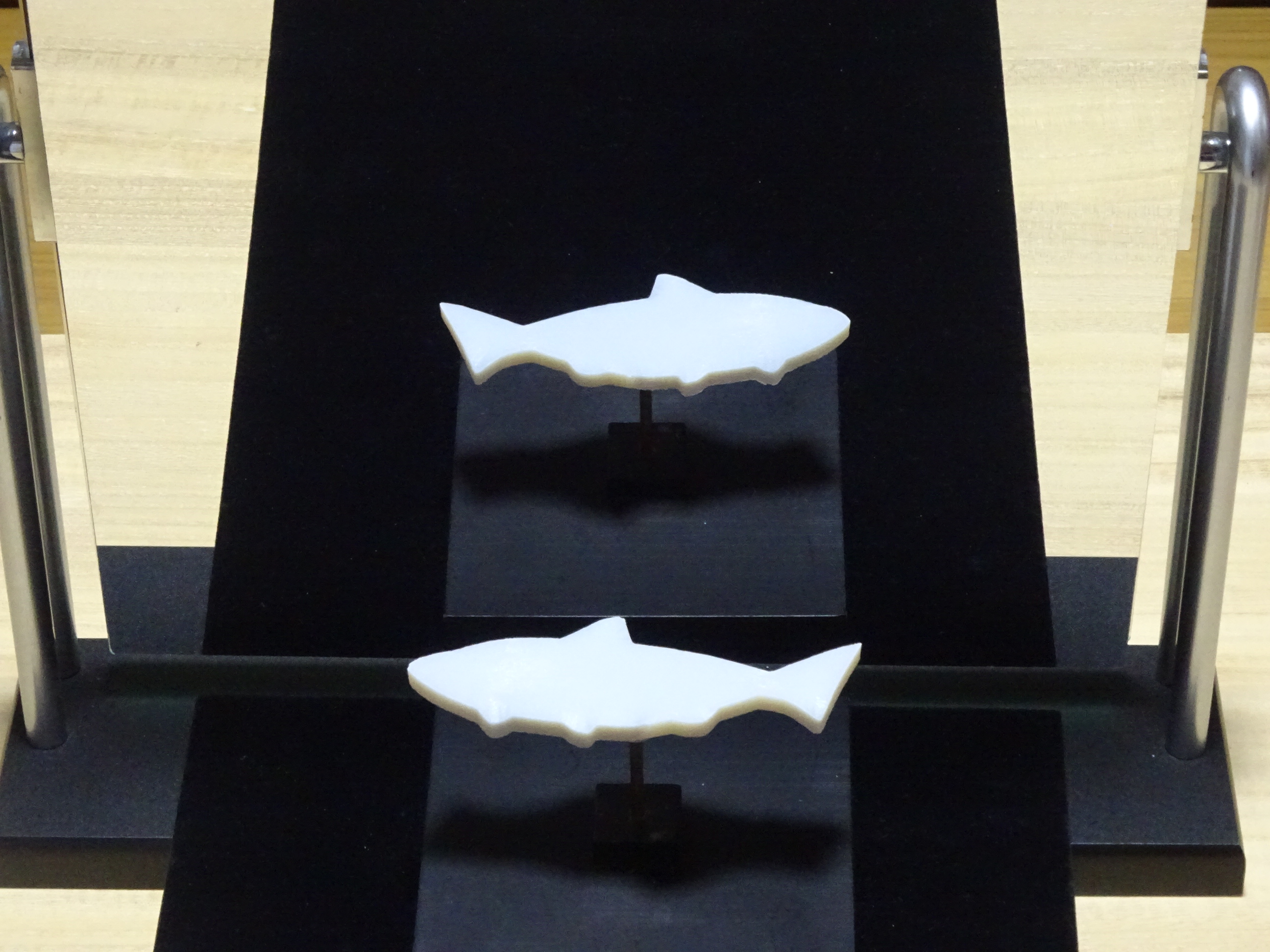
Figures 5, 6 and 7 show three more examples of left-right reversing objects computed by the method described above. The object in Figure 5 is a fish facing towards the left, which however faces towards the right in the mirror. Note that the upper and lower boundary curves of the fish shape are not symmetric with respect to the -axis.
In Figure 6 (a), a bird faces towards the right, but its mirror image faces towards the left. In this case, we gave the initial boundary curve of the bird shape on the -plane instead of on the -plane, so that the resulting bird is almost vertical instead of being almost horizontal. Figure 6 (b) and (c) present the front view and the side view, respectively, of this object.
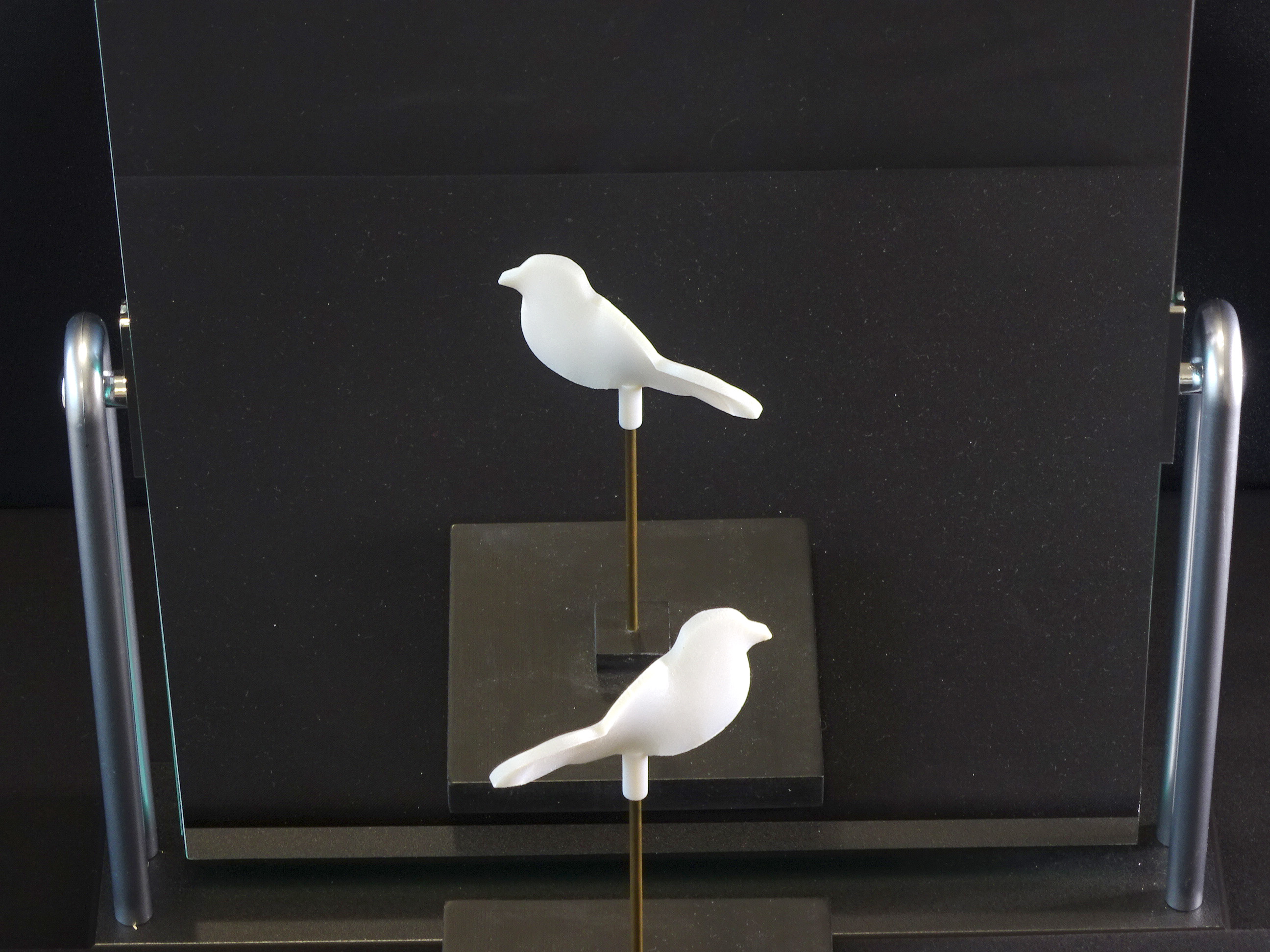


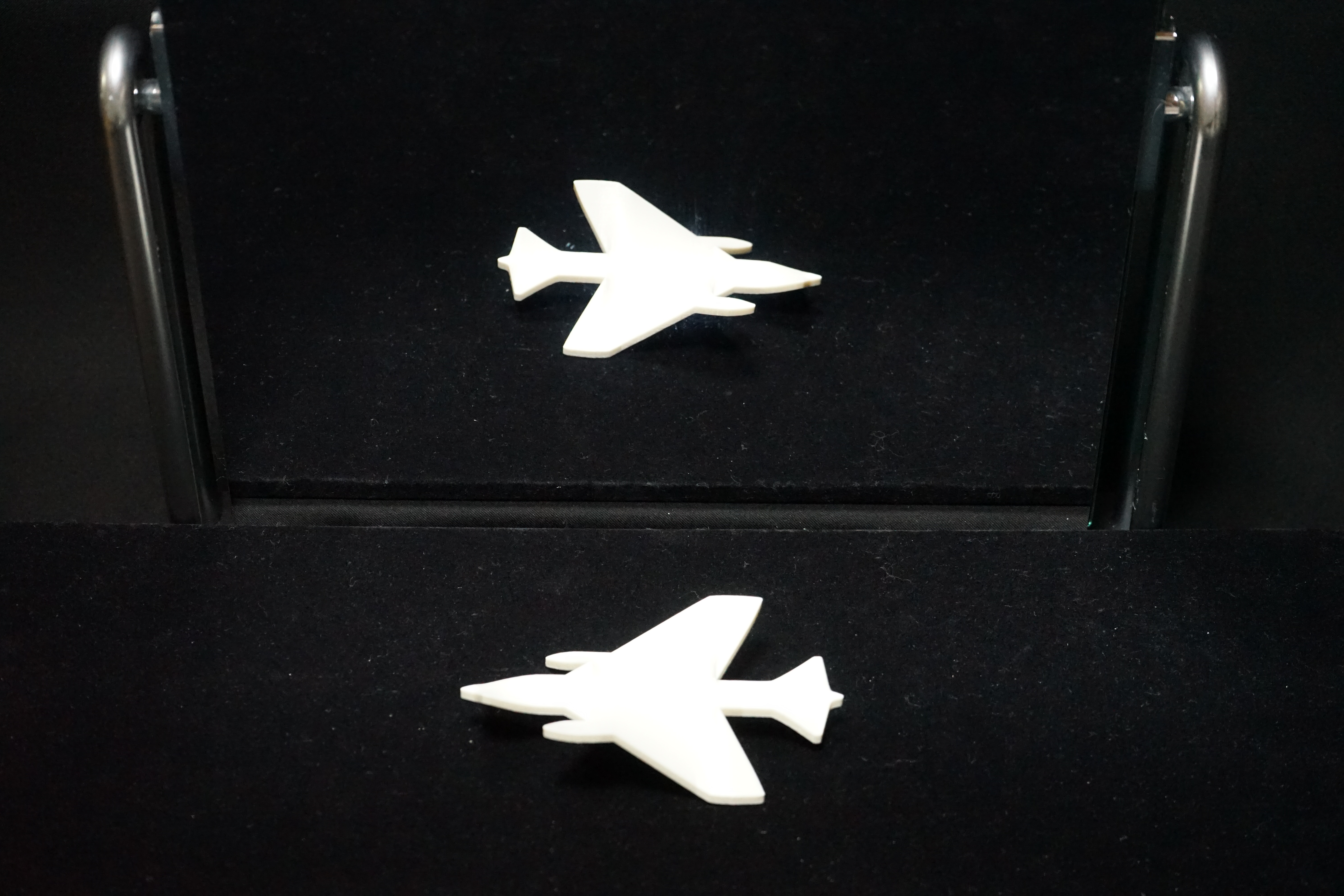
Figure 7 shows a jet airplane facing towards the left, but facing in the opposite direction in the mirror. In this case, the upper and lower boundaries are not -monotone, but we can nevertheless construct the object. Indeed, the monotonicity condition is too strong; what we need is a one-to-one correspondence between the points on the given curve and those with the same -coordinate on the 180° rotated curve.
In all examples, we first computed the space curve , and then added the thickness by translating in the direction perpendicular to the plane containing the initial curve . Thus, the translation is vertical in Figures 5 and 7, and horizontal in Figure 6.
4 Human factors of the illusion
Mathematically, the left-right reversal illusion is created by a line-symmetric 3D object. However, we also must consider human factors to strengthen the illusion.
In the objects shown in last section, we adopted a swept surface when the curve moves along a straight line. The reason is as follows: is a space curve and physically matches when it is seen in the viewing direction . However, there is no guarantee that is perceived. One may perceive , perceive , or perceive any other curve that matches in the viewing direction . Thus, we need some additional trick for the viewer to perceive instead of any other possible interpretations.
For this purpose, we used a remarkable characteristic of the human vision system, that is, the preference for rectangularity. The human brain prefers right angles to other angles when interpreting 2D pictures as 3D objects [4 D. N. Perkins, Visual discrimination between rectangular and nonrectangular parallelopipeds. Perception & Psychophysics 12, 293–331 (1972) , 5 D. N. Perkins, Compensating for distortion in viewing pictures obliquely. Perception & Psychophysics 14, 13–18 (1973) , 12 K. Sugihara and B. Pinna, Rectangularity is stronger than symmetry in interpreting 2D pictures as 3D objects. Frontiers in Human Neuroscience, DOI 10.3389/fnhum.2022.849159 (2022) ]. When we see a parallelogram, we are apt to interpret it as a rectangle seen in the slanted direction. This tendency is very strong and can be used to design various types of depth illusions, such as impossible motions [7 K. Sugihara, Design of solids for antigravity motion illusion. Comput. Geom. 47, 675–682 (2014) ], ambiguous cylinders [8 K. Sugihara, Design of ambiguous cylinders. In Asian Forum on Graphic Science (Bangkok, 2015), Electric Proceedings, Fo7 (2015) ], and topology-disturbing objects [10 K. Sugihara, Topology-disturbing objects: A new class of 3D optical illusion. J. Math. Arts 12, 2–18 (2018) ].
When is translated vertically, the swept surface forms a cylinder whose height is the same wherever we measure it. Therefore, we may expect that the viewer interprets the top curve as the section obtained when we cut the cylinder by the plane perpendicular to the axis. This section is identical to the original curve .
Another factor to note is the difference between a 3D object and its projected image. When we look at Figures 1, 5, 6 (a), and 7, most of us can enjoy the illusion without any special effort. However, we must note that these figures are 2D images taken by a camera. When we see an actual 3D object, in contrast, the illusion is not as strong because we have stereoscopic vision.
When we see a real object with two eyes, we can perceive the depth to the surface of the object by the triangulation principle [1 R. Gregory, The intelligent eye. Weidenfeld & Nicolson, London (1970) , 2 D. Marr, Vision. W. H. Freeman and Company, New York (1982) ]. This function is called binocular stereoscopic vision. Hence, we can figure out the actual shape of the object relatively easily.
When we see an image taken by a camera, however, binocular stereoscopic vision is not a factor in perceiving the image. A camera has only one set of lenses, and hence taking a picture with a camera is equivalent to seeing an object with one eye while closing the other. As a result, our brain needs to choose some 3D structure among many possibilities and usually chooses one that has many right angles. For this reason, the left-right reversal illusion can be perceived more strongly when we see projected images than when we see actual objects.
5 Construction by rectangular cylinders
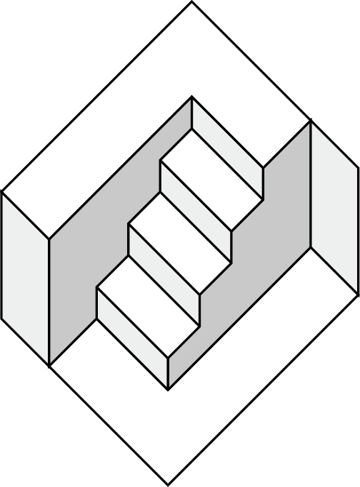
The left-right reversal illusion can be created when we construct a line-symmetric object. One simple way to accomplish this is to use a rectangular cylinder. The black lines in Figure 8 show a diagram of the unfolded surface of a rectangular cylinder. When we print it on a sheet of paper, fold it along the vertical lines, and glue it so that the left and right edges meet, we obtain a rectangular cylinder.

Next, as shown by the red lines in Figure 8, let us cut off the upper part in such a way that the leftmost side and the third side from the left are cut along the same curve, and the second and the fourth sides are cut along the straight lines connecting the end point of and the starting point of the other (the red broken lines in the figure). Then the resulting cylinder is a line-symmetric object whose line of symmetry is parallel to the axis of the cylinder and passes through the center of the rectangle section. Therefore, by placing the resulting cylinder vertically in front of a mirror and viewing it from a high angle, we can see the left-right reversal illusion.
Figure 9 shows the object constructed from the diagram in Figure 8. We painted the inner side of the cylinder in blue. The top of the cylinder appears to be a rocket facing towards the left, while it faces towards the right in the mirror. The thickness of the apparent shape as well as the lengths of the left- and right-side edges depend on the slant angle along which we look down at the object. In the case of Figure 9, we adjusted the viewing angle so that one of the side edges degenerates to a point and consequently the head of the rocket forms a sharp corner.

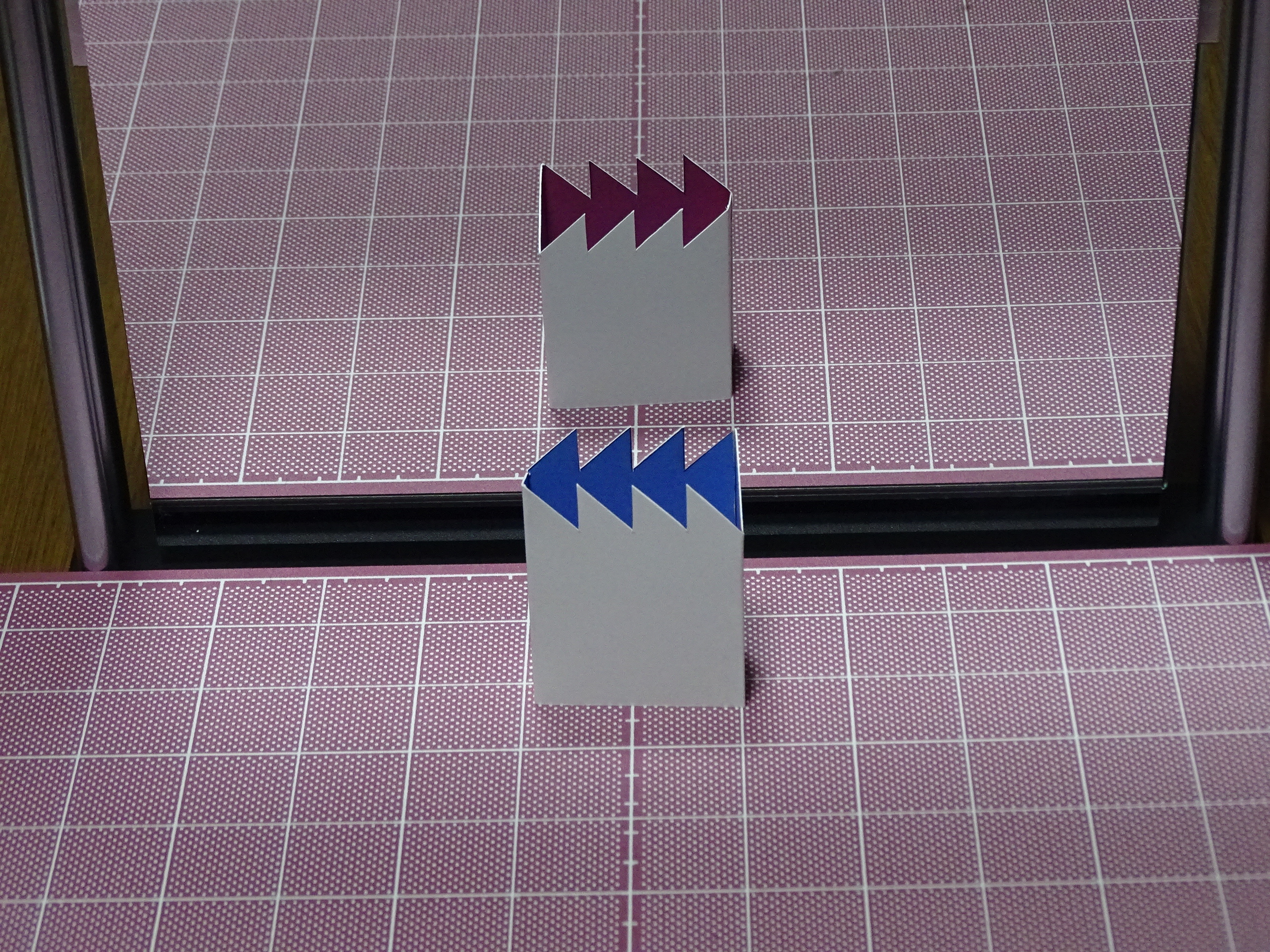
Figure 10 displays two more examples: (a) shows a fish and (b) shows a cascade of arrows. The colors in the mirror change simply because the inner side of each cylinder was painted in two colors.
The method is very simple. We need to use the same curve twice, as shown by the points labeled in Figure 8. Therefore, it might be fun even for children to search for the curves that can create their own original shapes.

6 Construction by pictures
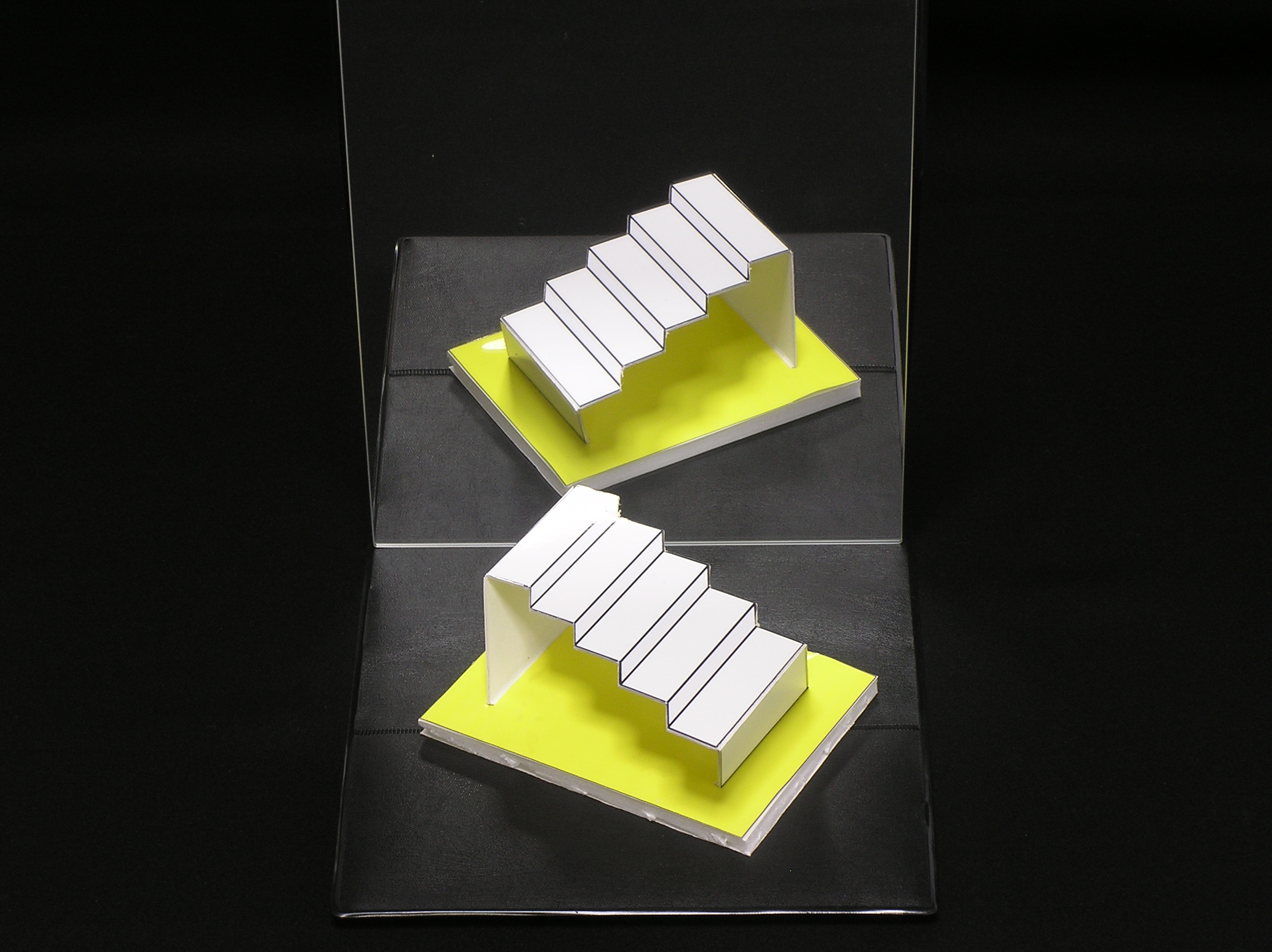
Another simple way to construct a line-symmetric object is to draw a picture. Figure 11 shows an example. The direct view of the drawing looks like a staircase going up from left to right, while in the mirror it goes up from right to left. Not only the staircase but also the upper and lower floors and walls are all left-right reversed in the mirror.

The drawing used in Figure 11 is shown in Figure 12. Note that this drawing is point-symmetric: if we rotate it by 180° around the center, we get the same picture as the initial image. This in turn means that the picture is line-symmetric with respect to the line that passes through the center of the drawing and is perpendicular to the picture plane. Therefore, the left and the right are reversed in the mirror because of the same reason as described above.
However, the perceptual process is a little more complicated because our brain automatically interprets 2D pictures as 3D objects when we look at the scene in Figure 11. If one does not interpret the drawing as a 3D structure, one could easily understand Figure 11, because the drawing in Figure 12 is just reflected by the mirror. In fact, the nearest point of the drawing is mapped to the farthest point in the mirror. However, the human brain has a stronger preference for rectangles than for general parallelograms [4 D. N. Perkins, Visual discrimination between rectangular and nonrectangular parallelopipeds. Perception & Psychophysics 12, 293–331 (1972) , 5 D. N. Perkins, Compensating for distortion in viewing pictures obliquely. Perception & Psychophysics 14, 13–18 (1973) , 12 K. Sugihara and B. Pinna, Rectangularity is stronger than symmetry in interpreting 2D pictures as 3D objects. Frontiers in Human Neuroscience, DOI 10.3389/fnhum.2022.849159 (2022) ]. Thus, when we look at Figure 11, our brain perceives a 3D object instead of a 2D drawing, and realizes that the mirror image is inconsistent.
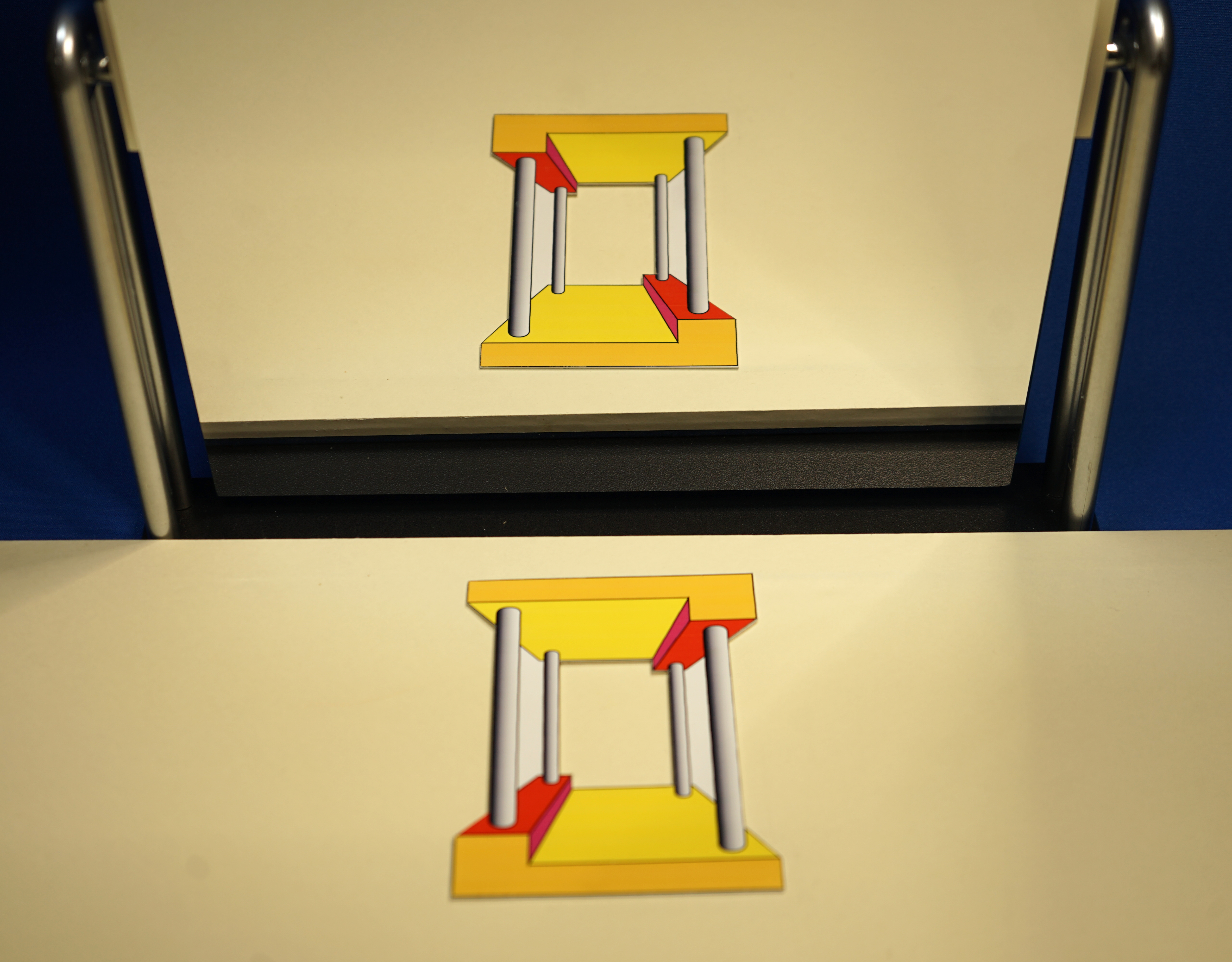
Another example is shown in Figure 13. This object is also a horizontally placed drawing, and it is point-symmetric with respect to the center, and hence line-symmetric with respect to a vertical line. However, it is a perspective projection instead of the orthographic projection of a 3D object, and consequently, the impression of 3D structure is strong. Physically, the nearest part is mapped to the farthest part in the mirror. However, because we interpret the nearest part as the lowest part of the 3D structure, we try to find the corresponding counterpart around the nearest area in the mirror and fall into an inconsistent perception.
The final example, shown in Figure 14, is a mixture of a horizontal drawing and an actual 3D structure. The staircase is a drawing fixed horizontally, with only the side walls not horizontal. The whole structure is line-symmetric with respect to a vertical line, and as a result, we can perceive the left-right reversal illusion.
7 Concluding remarks
We have demonstrated how a line-symmetric 3D structure can create a left-right reversal illusion and presented a method for designing illusion objects with desired appearances. We also presented two simple classes of line-symmetric structures: rectangular cylinders and point-symmetric 2D pictures. These simple classes can offer material for anyone, even for children, to create their own illusion objects, and to experience the illusion.
From an educational point of view, these two simple classes of illusion objects enjoy several advantages. First, children can create their own objects instead of just being handed existing objects. This may stimulate their active involvement. Second, children can experience the illusion using real 3D objects instead of just viewing images taken by a camera. This should provide an opportunity to understand the difference between seeing objects and seeing their images, and thus help children understand the importance of having two eyes. Third, illusion objects can give children an opportunity to understand the power of mathematics, which provides a framework to create illusions in a systematic manner rather than by heuristics.
Optical illusions in general cover a wide range of visual phenomena, including misperception of size, orientation, shape, color, brightness, and motion. Among them, the depth illusion, which includes the left-right reversal illusion, is remarkable in that the mechanism can be understood from a mathematical point of view more clearly than other classes of optical illusions. Indeed, the interpretation of 2D retinal images as 3D objects is an ill-defined problem, in the sense that the answer is not unique [2 D. Marr, Vision. W. H. Freeman and Company, New York (1982) , 6 K. Sugihara, Machine interpretation of line drawings. MIT Press, Cambridge (1986) ], and by observing the behavior of human visual perception, we can guess what kind of possibilities are chosen more frequently. This understanding also helps us create new optical illusions. The left-right reversal illusion is one of the common illusions that can be discovered using mathematics.
Acknowledgements. This work was supported by the Japan Society for the Promotion of Science, KAKENHI Grant Nos. JP21H03530 and JP21K19801.
References
- R. Gregory, The intelligent eye. Weidenfeld & Nicolson, London (1970)
- D. Marr, Vision. W. H. Freeman and Company, New York (1982)
- J. Ninio, The science of illusions (English translation). Cornell University Press, Ithaca (2001)
- D. N. Perkins, Visual discrimination between rectangular and nonrectangular parallelopipeds. Perception & Psychophysics 12, 293–331 (1972)
- D. N. Perkins, Compensating for distortion in viewing pictures obliquely. Perception & Psychophysics 14, 13–18 (1973)
- K. Sugihara, Machine interpretation of line drawings. MIT Press, Cambridge (1986)
- K. Sugihara, Design of solids for antigravity motion illusion. Comput. Geom. 47, 675–682 (2014)
- K. Sugihara, Design of ambiguous cylinders. In Asian Forum on Graphic Science (Bangkok, 2015), Electric Proceedings, Fo7 (2015)
- K. Sugihara, Anomalous mirror symmetry generated by optical illusion. Symmetry 8, Article ID 21, DOI 10.3390/sym8040021 (2016)
- K. Sugihara, Topology-disturbing objects: A new class of 3D optical illusion. J. Math. Arts 12, 2–18 (2018)
- K. Sugihara, Family tree of impossible objects created by optical illusion. In Brindges 2020 Conference Proceedings, 329–336, http://archive.bridgesmathart.org/2020/bridges2020-329.pdf (2020)
- K. Sugihara and B. Pinna, Rectangularity is stronger than symmetry in interpreting 2D pictures as 3D objects. Frontiers in Human Neuroscience, DOI 10.3389/fnhum.2022.849159 (2022)
Cite this article
Kokichi Sugihara, Left-right reversal illusion. Eur. Math. Soc. Mag. 125 (2022), pp. 13–19
DOI 10.4171/MAG/96